Difference between revisions of "BalanceBoard Lab"
| Line 34: | Line 34: | ||
{| | {| | ||
|- | |- | ||
| − | | [[File:Capture2.JPG| | + | | [[File:Capture2.JPG|600px|Image: 600 pixels]] |
|} | |} | ||
Revision as of 09:57, 25 March 2015
Balance board

|
Introduction
A balance board(force platform) is commonly used in motor control labs and neurologic clinics. They essentially consist of a set of finely calibrated scales, measuring mechanical forces. The pattern of forces can be used to derive body position, at a high spatial and temporal resolution.
Description
There are several boards specified up to 1M2 and 0,5M2 with a sub-millimeter spatial resolution and a 200 hz temporal resolution.
A typical balance board records at a high spatial and temporal resolution. Regarding spatial resolution: a platform can detect changes from a few sub-millimeters (freezing) to at least 500 centimeter (forward or backward steps). The platform records reliably over four vertical forces. Regarding temporal resolution: the signals are typically sampled at 200 Hz. Even though the system allows even higher sampling rates, in practice 100 Hz is sufficient.
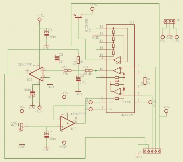
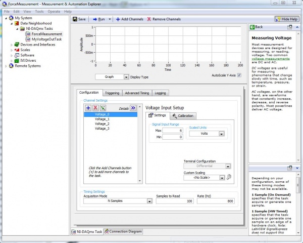
The pressure sensors derive directly from the wii balance board. Each sensor has a maximum pressure of 120Kg. In-house electronics is build to get a clean amplification from the sensors. A National instruments card, USB-6221, takes care of the A/D conversion and connects with usb to a pc. The force plate can be integrated into existing systems for stimulus presentation and for recording bodily signals such as EEG, EMG and heart rate. In practice, this means that the systems are time-locked within millisecond accuracy.
Instructions
Find the BalanceboardCalibration manual here Media:SOP_1_BalanceboardCalibration.pdf
Find the BalanceBoardBaseline manual here Media:SOP_2_BalanceBoardBaseline.pdf
Find the InstructionPosture manual here Media:SOP_3_InstructionPosture.pdf
Technical design

|
National instruments settings

|
Presentation software
sub runtrials_national begin # The dio_device will setup NI-DAQmx device number 1 "Dev1" dio_device card = new dio_device(ni_dio_device, 1, 0 ); #int id = card.acquire_analog_input( "MyVoltageOutTask" ); int id1 = card.acquire_analog_input( "ForceMeasurement,Voltage_0" ); int id2 = card.acquire_analog_input( "ForceMeasurement,Voltage_1" ); int id3 = card.acquire_analog_input( "ForceMeasurement,Voltage_2" ); int id4 = card.acquire_analog_input( "ForceMeasurement,Voltage_3" ); count_old = response_manager.total_response_count(); loop until false begin if response_manager.total_response_count() > count_old then count_old = response_manager.total_response_count(); calibrate_board = true; end; message_scale[1] = round(round(card.read_analog( id1, 1000.0 ),6) * 1000.0, 0); message_scale[2] = round(round(card.read_analog( id2, 1000.0 ),6) * 1000.0, 0); message_scale[3] = round(round(card.read_analog( id3, 1000.0 ),6) * 1000.0, 0); message_scale[4] = round(round(card.read_analog( id4, 1000.0 ),6) * 1000.0, 0); if calibrate_board then zero_scale_left_up = message_scale[left_up]; zero_scale_left_down = message_scale[left_down]; zero_scale_right_up = message_scale[right_up]; zero_scale_right_down = message_scale[right_down]; calibrate_board = false; end; message_scale[left_up] = message_scale[left_up] - zero_scale_left_up; message_scale[left_down] = message_scale[left_down] - zero_scale_left_down; message_scale[right_up] = message_scale[right_up] - zero_scale_right_up; message_scale[right_down] = message_scale[right_down] - zero_scale_right_down; t_scale11.set_caption(string(message_scale[left_up])); t_scale11.redraw(); t_scale22.set_caption(string(message_scale[left_down])); t_scale22.redraw(); t_scale33.set_caption(string(message_scale[right_up])); t_scale33.redraw(); t_scale44.set_caption(string(message_scale[right_down])); t_scale44.redraw(); pos_dot_x = (message_scale[right_up] + message_scale[right_down]) - message_scale[left_up] + message_scale[left_down]); pos_dot_y = (message_scale[left_up] + message_scale[right_up]) - message_scale[left_down] + message_scale[right_down]); p_balance.add_part( balance_pos, (pos_dot_x * 1.0), (pos_dot_y * 1.0)); t_coord.set_caption(string(pos_dot_x)+","+string(pos_dot_y)); t_coord.redraw(); p_balance.present(); p_balance.remove_part( 8 ); end; card.release_analog_input( id1 ); card.release_analog_input( id2 ); card.release_analog_input( id3 ); card.release_analog_input( id4 ); end;
Python software
from PyDAQmx import Task from PyDAQmx.DAQmxConstants import * from PyDAQmx.DAQmxTypes import * import numpy import msvcrt import time times = [] try : freq = 100.0 # Hz numinputs = 4 analog_input = Task() read = int32() timer= time.clock() running = True data = numpy.zeros((numinputs,), dtype=numpy.float64) #DAQmx Configure Code analog_input.CreateAIVoltageChan("Dev1/ai0:%i" % (numinputs - 1), None, DAQmx_Val_RSE, -10.0,10.0,DAQmx_Val_Volts,None) #analog_input.CfgInputBuffer(0) #analog_input.CfgSampClkTiming("",freq,DAQmx_Val_Rising,DAQmx_Val_ContSamps,1000) analog_input.StartTask() datalist = [] while running: #DAQmx Start Code timeBeforeRead = time.clock() analog_input.ReadAnalogF64(-1,10.0,DAQmx_Val_GroupByChannel,data,numinputs*2,byref(read),None) ser.write('S') line = ser.readline() time.sleep((1 / freq) - (time.clock()- timeBeforeRead)) times.append(timeBeforeRead - time.clock()) if msvcrt.kbhit(): running = False finally : print "Stop" t = numpy.array(times) afwijking = numpy.mean(abs(t - numpy.mean(t))) maxafwijking = max(abs(t-numpy.mean(t))) print numpy.mean(t), afwijking, maxafwijking analog_input.StopTask();