Difference between revisions of "ButtonBoxes"
Wiki-admin (talk | contribs) |
Wiki-admin (talk | contribs) |
||
| (17 intermediate revisions by 3 users not shown) | |||
| Line 1: | Line 1: | ||
{{Infobox tsg | {{Infobox tsg | ||
| − | | name = Buttonbox | + | | name = Buttonbox (2018) |
| − | | image = | + | | image = Buttonbox_2018_1.png |
| caption = 2018 Buttonbox | | caption = 2018 Buttonbox | ||
| downloads = {{bulleted list | | downloads = {{bulleted list | ||
| − | | [ | + | | [https://surfdrive.surf.nl/files/index.php/s/PPTKCyrjLkN4XUO Buttonbox 2018] |
| − | |||
| − | |||
| [https://pypi.python.org/pypi/RuSocSci RuSocSci] (Python package) | | [https://pypi.python.org/pypi/RuSocSci RuSocSci] (Python package) | ||
}} | }} | ||
| Line 15: | Line 13: | ||
| caption = 2013 Buttonbox | | caption = 2013 Buttonbox | ||
| downloads = {{bulleted list | | downloads = {{bulleted list | ||
| − | | [ | + | | [https://surfdrive.surf.nl/files/index.php/s/72XEcu2XKSgzxjp Buttonbox 2015] |
| − | |||
| [https://pypi.python.org/pypi/RuSocSci RuSocSci] (Python package) | | [https://pypi.python.org/pypi/RuSocSci RuSocSci] (Python package) | ||
}} | }} | ||
| Line 65: | Line 62: | ||
===Output=== | ===Output=== | ||
| − | Output knows two protocols: '''BITSI simple''' or '''BITSI extended'''. To enter a certain protocol two buttons have to be pressed when the BITSIbox is powered. '''[2015]Press button H and A for simple mode and H and B for extended mode.[2018]Press button E and A for simple mode and E and B for extended mode.''' | + | Output knows two protocols: '''BITSI simple''' or '''BITSI extended'''. To enter a certain protocol two buttons have to be pressed when the BITSIbox is powered or com port opens. '''[2015]Press button H and A for simple mode and H and B for extended mode. [2018]Press button E and A for simple mode and E and B for extended mode.''' |
If no button is pressed when powered it boots the last known protocol. In the simple protocol every byte sent to the BITSI over the serial port, is represented at the 8 bit output. | If no button is pressed when powered it boots the last known protocol. In the simple protocol every byte sent to the BITSI over the serial port, is represented at the 8 bit output. | ||
| Line 226: | Line 223: | ||
=== Python/PsychoPy === | === Python/PsychoPy === | ||
| − | Download this site-package to use the buttonbox: [https://pypi.python.org/pypi/RuSocSci rusocsci] | + | Download this site-package to use the buttonbox: [https://pypi.python.org/pypi/RuSocSci rusocsci] |
| + | |||
| + | or use in windows command 'pip install --upgrade rusocsci' | ||
'''Example using buttons from the buttonbox in Python:''' | '''Example using buttons from the buttonbox in Python:''' | ||
| Line 273: | Line 272: | ||
# select a function | # select a function | ||
| − | bb.sendMarker(val=(ord(X))) | + | bb.sendMarker(val=(ord('X'))) #select pulse time |
bb.sendMarker(val=2) #set time of dureation pulse to 2ms | bb.sendMarker(val=2) #set time of dureation pulse to 2ms | ||
| − | bb.sendMarker(val=(ord(M))) | + | bb.sendMarker(val=(ord('M'))) #select marker out |
| − | bb.sendMarker(val=115) | + | bb.sendMarker(val=115) #set marker value 115 |
</syntaxhighlight> | </syntaxhighlight> | ||
| Line 290: | Line 289: | ||
# make a buttonbox | # make a buttonbox | ||
ser = serial.Serial("COM2", 115200, timeout = 0.10 ) | ser = serial.Serial("COM2", 115200, timeout = 0.10 ) | ||
| + | ser = serial.Serial("/dev/ttyUSB0", 115200, timeout = 0.10 ) | ||
while True: | while True: | ||
| Line 339: | Line 339: | ||
For more documentation click here: http://pythonhosted.org//RuSocSci/index.html | For more documentation click here: http://pythonhosted.org//RuSocSci/index.html | ||
| + | <br> | ||
| + | <br> | ||
=== Matlab === | === Matlab === | ||
| + | '''Example using markers with the Buttonbox in Matlab:''' | ||
| − | <syntaxhighlight lang="matlab" line style=" | + | Download the file Bitsi.m from the DCCN website: https://intranet.donders.ru.nl/index.php?id=bitsim0 |
| − | + | <br> Make sure to have this file in your Matlab path. | |
| − | + | <syntaxhighlight lang="matlab" line style="overflow:auto;"> | |
| − | + | % At the start of your script, create the buttonbox serial object | |
| − | + | bb = Bitsi("COM2"); | |
| − | + | % other code | |
| − | + | : | |
| − | + | </syntaxhighlight> | |
| − | |||
| − | |||
| − | % | ||
| − | |||
| − | |||
| − | |||
| − | |||
| − | |||
| − | |||
| − | |||
| − | |||
| − | |||
| − | |||
| − | |||
| − | |||
| − | |||
| − | |||
| − | |||
| − | |||
| − | + | BITSI simple mode: | |
| − | % | + | <syntaxhighlight lang="matlab" line style="overflow:auto;"> |
| − | bb. | + | % This example is for an EEG system sampling at 500Hz samplerate. |
| − | + | % at the start of your script, reset marker | |
| − | bb. | + | samplerate = 500; |
| − | + | pulseLen = 2000/samplerate; % get pulse time length for a 2 samples delay | |
| − | bb. | + | bb.sendTrigger(0); |
| + | % send a marker | ||
| + | val = 1; % val: this is your marker code, range code 1-255 | ||
| + | bb.sendTrigger(val); | ||
| + | java.lang.Thread.sleep(pulseLen); % wait long enough for the EEG system to capture the trigger, i.e., 2000/samplerate ms | ||
| + | % reset marker | ||
| + | bb.sendTrigger(0) % Note: if resetting the marker is not possible at this moment in code, you can decide to do this later as long as it has taken place long enough before the next marker has to be sent. Another solution using a timer object instead of a simple delay is outlined below. | ||
| + | </syntaxhighlight> | ||
| − | + | BITSI extended mode: | |
| − | + | <syntaxhighlight lang="matlab" line style="overflow:auto;"> | |
| − | + | samplerate = 500; | |
| − | + | pulseLen = 2000/samplerate; % get pulse time length for a 2 samples delay | |
| − | + | % select a function | |
| − | + | bb.sendTrigger(uint8('X')); % select pulse time | |
| − | + | bb.sendTrigger(pulseLen); % set time of duration pulse to (2000/samplerate) ms | |
| − | + | ||
| − | + | val = 1; % val: this is your marker code, range code 1-255 | |
| − | + | bb.sendTrigger(uint8('M')); % select marker out | |
| − | + | bb.sendTrigger(val); % val: this is your marker code, range code 1-255 | |
| − | + | </syntaxhighlight> | |
| − | |||
| − | |||
| − | |||
| − | |||
| − | |||
| − | |||
| − | + | <syntaxhighlight lang="matlab" line style="overflow:auto;"> | |
| − | + | % At the end of your script, close the buttonbox serial object | |
| − | + | : | |
| − | + | bb.close(); | |
| − | + | </syntaxhighlight> | |
| − | |||
| − | |||
| − | + | Reset marker using a timer: | |
| − | + | <syntaxhighlight lang="matlab" line style="overflow:auto;"> | |
| − | + | % At the start of your script, define timer object and callback function | |
| − | + | pulseTime = 0.004; % trigger pulse duration in s. NB: extra time will be added due to overhead in calling Matlab functions related to the timer event. | |
| − | + | resetMarker = timer('TimerFcn',@(x,y)bb.sendTrigger(0),'StartDelay',pulseTime); | |
| − | |||
| − | |||
| − | |||
| − | |||
| − | |||
| − | |||
| − | |||
| − | |||
| − | |||
| − | |||
| − | |||
| − | |||
| − | |||
| − | |||
| − | |||
| − | |||
| − | |||
| − | |||
| − | |||
| − | |||
| − | |||
| − | |||
| − | |||
| − | |||
| − | |||
| − | |||
| − | |||
| − | |||
| − | |||
| − | |||
| − | |||
| − | |||
| − | |||
| − | |||
| − | |||
| − | |||
| − | |||
| − | |||
| − | |||
| − | |||
| − | |||
| − | |||
| − | |||
| − | |||
| − | |||
| − | |||
| − | |||
| − | |||
| − | % | + | % replace the code to send a marker with: |
| − | + | val = 1; % val: this is your marker code, range code 1-255 | |
| − | + | bb.sendTrigger(val); | |
| − | + | resetMarker.start(); % this will call bb.sendTrigger(0) after pulseTime seconds (plus some additional overhead) | |
| − | |||
| − | |||
| − | |||
| − | |||
| − | |||
| − | |||
| − | |||
| − | |||
| − | |||
| − | |||
| − | |||
| − | |||
| − | |||
| − | |||
| − | |||
| − | |||
| − | |||
| − | |||
| − | |||
| − | |||
| − | |||
| − | |||
| − | |||
| − | |||
| − | |||
| − | |||
| − | |||
| − | |||
| − | + | </syntaxhighlight> | |
| − | |||
| − | |||
| − | |||
| − | |||
| − | |||
| − | |||
| − | |||
| − | |||
| − | |||
| − | |||
| − | |||
| − | |||
| − | |||
| − | |||
| − | |||
| − | |||
| − | |||
| − | |||
| − | |||
| − | |||
| − | |||
| − | |||
| − | |||
| − | |||
| − | |||
| − | |||
| − | |||
| − | |||
| − | |||
| − | |||
| − | |||
| − | |||
| − | |||
| − | |||
| − | |||
| − | |||
| − | |||
| − | |||
| − | |||
| − | |||
| − | |||
| − | |||
| − | |||
| − | |||
| − | |||
| − | |||
| − | |||
| − | |||
| − | |||
| − | |||
| − | |||
| − | |||
| − | |||
Latest revision as of 12:27, 21 November 2023
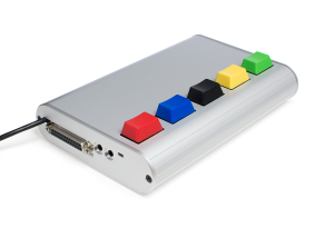 2018 Buttonbox | |
| Downloads | |
|---|---|
|
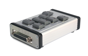 2013 Buttonbox | |
| Downloads | |
|---|---|
|
The buttonbox is used for time accurate(1ms) button press registration. We use it to register buttonpresses, soundkey, voicekey signals and to send tone onset, analog output, triggers with the BITSI protocol. It is suitable for Behavioral, EEG, MEG, and fMRI experiments. The buttonbox is connected to a computer with a usb connection.
The output connector has two binary eight bit ports: input and output. The two ports can be used for responses (input) and stimulus triggers (output). Two 12 bits analog outputs and three 12 bits analog inputs. The output connector has a sound and voicekey which triggers when a amplitude reaches a threshold. By using the serial port, the BITSI can be used platform independently: it works on Windows, Linux and Mac OSX. Most programming environments and stimulus packages support serial communication.
There is currently a Microsoft Windows driver issue.
BITSI Protocol
BITSI stands for Bits to Serial Interface. Because the BITSI is designed to interface both in- and output signals, the 'protocol' is asymmetric: the input and output protocols differ.
Input
The input port can be used to interface eight buttons maximally. Button presses are translated to serial output characters/bytes according to the following table:
| BITSI Simple | ||
|---|---|---|
| Signal/Button | ASCII (rise/fall) | Code (rise/fall) |
| 1 | A / a | 65 / 97 |
| 2 | B / b | 66 / 98 |
| 3 | C / c | 67 / 99 |
| 4 | D / d | 68 / 100 |
| 5 | E / e | 69 / 101 |
| 6 | F / f | 70 / 102 |
| 7 | G / g | 71 / 103 |
| 8 | H / h | 72 / 104 |
This means that when signal 1 gets active(button press), a capital A will be sent to the serial port. A lowercase 'a' will be sent when the signal is deactivated(button release). Mechanical buttons can be connected directly.
Output
Output knows two protocols: BITSI simple or BITSI extended. To enter a certain protocol two buttons have to be pressed when the BITSIbox is powered or com port opens. [2015]Press button H and A for simple mode and H and B for extended mode. [2018]Press button E and A for simple mode and E and B for extended mode.
If no button is pressed when powered it boots the last known protocol. In the simple protocol every byte sent to the BITSI over the serial port, is represented at the 8 bit output.
The extended protocol uses two bytes(or two characters), this combination can access two analog outputs and a tone generator. The first byte selects the output. The second byte determines the value written to this output.
| BITSI Extended | ||
|---|---|---|
| Function | Byte 1 (ASCII/code) | Byte 2 |
| Marker Out | M / 77 | Marker Value |
| Pulse Out | P / 80 | Marker Value |
| Pulse Time | X / 88 | ms before pulse reset |
| Analog Out 1 | Y / 89 | Analog Output Value |
| Analog Out 2 | Z / 90 | Analog Output Value |
| Tone | T / 84 | Start Tone |
| Detect Sound | D / | S / 83 |
| Detect Voice | D / | V / 83 |
| Calibrate Sound | C / | S |
| Calibrate Voice | C / | V |
| Analog In 1 | A / | 1 |
| Analog In 2 | A / | 2 |
| Analog In 3 | A / | 3 |
| Analog In 4 | A / | 4 |
| LEDs Off | L / | X |
| LEDs Input | L / | I |
| LEDs Output | L / | O |
Port Settings
Trigger port
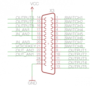
The 25 pins female connector has 8 inputs and 8 outputs, respectively 1-8 are inputs and 9-16 are outputs. Three analog input with an analog to digital convertor of 12 bit, pins 17,18,20 and 21. Two analog outputs with an digital to analog convertor of 12 bits on pins 22 and 23.
The inputs 1-8 will be pulled down from 5V to GND when the buttons are pressed. The outputs 9-16 will be pulled up from GND to 5V when the output is activated.
Serial port
Our hardware design allows to be connected to the computers USB and emulates a serial communication Port.
| Baudrate | 115200 |
| Parity | None |
| Data bits | 8 |
| Stop bits | 1 |
| Flow control | None |
USB-Com port
1.Connect the BITSIbox to your computer using the USB cable.
2.When you connect the BITSIbox, Windows should initiate the driver installation process (if you haven't used the computer with an BITSIbox board before).
3.On Windows Vista/7, the driver should be automatically downloaded and installed.
4.On Windows XP, the Add New Hardware wizard will open:
- When asked Can Windows connect to Windows Update to search for software? select No, not this time. Click next.
- Select Install from a list or specified location (Advanced) and click next.
- Make sure that Search for the best driver in these locations is checked; uncheck Search removable media; check Include this location in the search and browse to the c:/beheer/arduino/drivers directory.
- The wizard will search for the driver and then tell you that a "USB Serial Converter" was found. Click finish.
- The new hardware wizard will appear again. Go through the same steps and select the same options and location to search. This time, a "USB Serial Port" will be found.
How to Check the Com Port settings(important!)
- From the Start menu, open the Control Panel.
- From the control panel, open the System window.
- From the system properties window, go to the Hardware tab and click the Device Manager button.
- From the Device Manager window, click Ports (Com&LPT). You should now be able to see which Com Port the USB adapter is assigned to.
- If the Com Port is 10 or higher, you will have to change it to a lower port.
- From the Device Manager window, click on USB Serial Port (Com#). Click the Port Settings tab of the USB Serial Port Properties window, and then click the Advanced button.
- In the Advanced Settings window, use the scroll input to select a Com Port (select 10 or lower). Change Receive (bytes) and Transmit (bytes) to 64. Change the Latency Timer to 1.
- Click the OK button.
Always connect the usb device to the same port and your settings will be remembered.
Software Settings
Neurobs Presentation
The experiment files needs a few settings for the device to work:
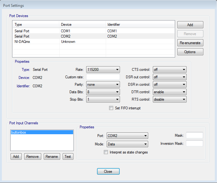
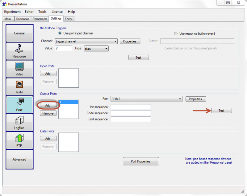
- In the settings tab: port -> input port -> 1 must be the device that identifies itself as "Arduino Uno" in the device manager. Note that the port must have a number not higher than 10 (COM1-COM10). Use re-enumerate if it is higher.
- Rate must be set 115200, Parity to None, Data Bits to 8 and Stop Bits to 1, Uncheck FIFO Interrupt.
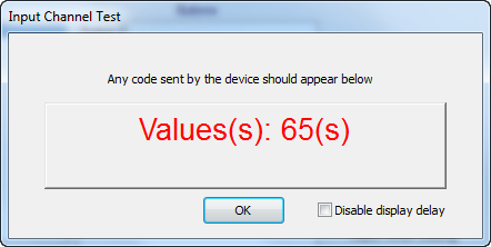
Testing Buttonbox
When pressing on the A button within the input channel tester. You will see the following ASCII code.
Adding Marker
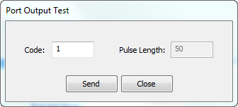
Testing Markers (output)
Send code 1 for Button A
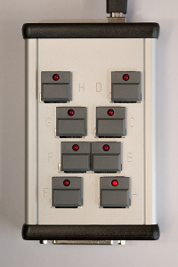
Button A will light up.
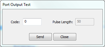
Send code 0 for clearing.
Example PCL code you can program a handle to send a marker:
#handle:
output_port OutputPort = output_port_manager.get_port( 1 );
Example to send a marker:
OutputPort.send_code(100); #create a marker
for more information see chapter 8 in the presentation course by clicking here
Python/PsychoPy
Download this site-package to use the buttonbox: rusocsci
or use in windows command 'pip install --upgrade rusocsci'
Example using buttons from the buttonbox in Python:
 1#!/usr/bin/env python
 2
 3# import the rusocsci.buttonbox module
 4from rusocsci import buttonbox
 5
 6# make a buttonbox
 7bb = buttonbox.Buttonbox()
 8
 9# wait for a single button press
10b = bb.waitButtons()
11
12# print the button pressed
13print("b: {}".format(b))
Example using markers with the buttonbox in Python:
 1#!/usr/bin/env python
 2
 3# import the rusocsci.buttonbox module
 4from rusocsci import buttonbox
 5
 6# make a buttonbox
 7bb = buttonbox.Buttonbox()
 8
 9# send a marker
10bb.sendMarker(val=100)    #This is your marker code, range code 1-255
Example using BITSI extended in Python:
 1#!/usr/bin/env python
 2
 3# import the rusocsci.buttonbox module
 4from rusocsci import buttonbox
 5
 6# make a buttonbox
 7bb = buttonbox.Buttonbox()
 8
 9# select a function
10bb.sendMarker(val=(ord('X')))  #select pulse time
11bb.sendMarker(val=2)           #set time of dureation pulse to 2ms
12
13bb.sendMarker(val=(ord('M')))  #select marker out
14bb.sendMarker(val=115)         #set marker value 115
Example using BITSI extended analog read in Python:
 1#!/usr/bin/env python
 2
 3# import the rusocsci.buttonbox module
 4import serial
 5
 6# make a buttonbox
 7ser = serial.Serial("COM2", 115200, timeout = 0.10 )
 8ser = serial.Serial("/dev/ttyUSB0", 115200, timeout = 0.10 )
 9
10while True:
11	ser.write('A1')
12	ser.flush()
13	x = ser.readline()
14	visual.TextStim(win, text=x).draw()
15
16	# black screen for 1000 ms
17	win.flip()
18
19	key = event.getKeys()
20	try:
21		if key[0]=='escape':
22			break
23	except:
24		continue
Example using the Buttonbox in PsychoPy:
 1#!/usr/bin/env python
 2
 3# import psychopy and rusocsci
 4from psychopy import core, visual
 5from rusocsci import buttonbox
 6
 7## Setup Section
 8win = visual.Window(monitor="testMonitor")
 9bb = buttonbox.Buttonbox()
10text = visual.TextStim(win, "Press a button on the buttonbox")
11
12## Experiment Section
13# show text
14text.draw()
15win.flip()
16# wait for response
17b = bb.waitButtons()
18# show response
19text.setText("you pressed: {}".format(b))
20text.draw()
21win.flip()
22core.wait(5)
23
24## Cleanup Section
25core.quit()
For more documentation click here: http://pythonhosted.org//RuSocSci/index.html
Matlab
Example using markers with the Buttonbox in Matlab:
Download the file Bitsi.m from the DCCN website: https://intranet.donders.ru.nl/index.php?id=bitsim0
Make sure to have this file in your Matlab path.
1% At the start of your script, create the buttonbox serial object
2bb = Bitsi("COM2");
3% other code
4        :
BITSI simple mode:
 1% This example is for an EEG system sampling at 500Hz samplerate.
 2% at the start of your script, reset marker
 3samplerate = 500;
 4pulseLen = 2000/samplerate; % get pulse time length for a 2 samples delay
 5bb.sendTrigger(0);
 6% send a marker
 7val = 1;                                     % val: this is your marker code, range code 1-255
 8bb.sendTrigger(val);
 9java.lang.Thread.sleep(pulseLen);    % wait long enough for the EEG system to capture the trigger, i.e., 2000/samplerate ms
10% reset marker
11bb.sendTrigger(0)                 % Note: if resetting the marker is not possible at this moment in code, you can decide to do this later as long as it has taken place long enough before the next marker has to be sent. Another solution using a timer object instead of a simple delay is outlined below.
BITSI extended mode:
1samplerate = 500;
2pulseLen = 2000/samplerate; % get pulse time length for a 2 samples delay
3% select a function
4bb.sendTrigger(uint8('X'));   % select pulse time
5bb.sendTrigger(pulseLen);             % set time of duration pulse to (2000/samplerate) ms
6
7val = 1;                                     % val: this is your marker code, range code 1-255
8bb.sendTrigger(uint8('M'));  % select marker out
9bb.sendTrigger(val);              % val: this is your marker code, range code 1-255
1% At the end of your script, close the buttonbox serial object
2    :
3bb.close();
Reset marker using a timer:
1% At the start of your script, define timer object and callback function
2pulseTime = 0.004; % trigger pulse duration in s. NB: extra time will be added due to overhead in calling Matlab functions related to the timer event.
3resetMarker = timer('TimerFcn',@(x,y)bb.sendTrigger(0),'StartDelay',pulseTime);
4
5% replace the code to send a marker with:
6val = 1;                                     % val: this is your marker code, range code 1-255
7bb.sendTrigger(val);
8resetMarker.start(); % this will call bb.sendTrigger(0) after pulseTime seconds (plus some additional overhead)
