Difference between revisions of "Vertical Sync sensor"
Wiki-admin (talk | contribs) |
|||
| (33 intermediate revisions by one other user not shown) | |||
| Line 1: | Line 1: | ||
{{Infobox tsg | {{Infobox tsg | ||
| − | | name = | + | | name = Vertical Sync sensor |
| − | | image = | + | | image = sensorPic.jpg |
| − | | caption = | + | | caption = Vertical Sync sensor |
| + | }} | ||
| + | {{Infobox tsg | ||
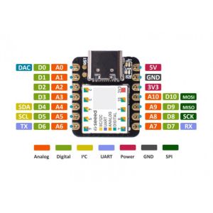
| + | | name = Seeed Studio XIAO SAMD21 | ||
| + | | image = Seeeduino_XIAO.JPG | ||
| + | | caption = Seeed Studio XIAO SAMD21 | ||
| + | | downloads = {{bulleted list | ||
| + | | [https://wiki.seeedstudio.com/Seeeduino-XIAO/ product_page] | ||
| + | }} | ||
| + | }} | ||
| + | {{Infobox tsg | ||
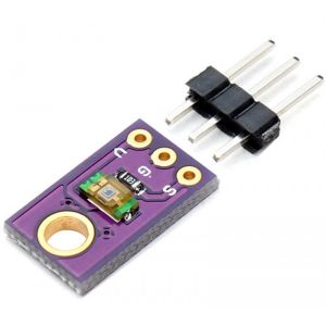
| + | | name = TEMT6000 Licht Sensor Module | ||
| + | | image = temt6000.jpg | ||
| + | | caption = TEMT6000 Licht Sensor Module | ||
| downloads = {{bulleted list | | downloads = {{bulleted list | ||
| − | | [https://surfdrive.surf.nl/files/index.php/s/ | + | | [https://surfdrive.surf.nl/files/index.php/s/Mpdr2DGEFlwetag Datasheet] |
| − | |||
}} | }} | ||
}} | }} | ||
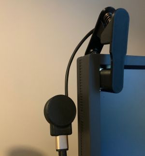
| − | The Vertical Sync sensor is used on a computer/laptop monitor for time accurate visual presentation. The sensor measures screen brightness. It generates a BITSI trigger("A" = ON/light, "a" = OFF/noLight) when the amount of light is higher than the (customizable) threshold | + | The Vertical Sync sensor is used on a computer/laptop monitor for time accurate visual presentation. The sensor measures screen brightness. It generates a BITSI trigger to the com-port("A" = ON/light, "a" = OFF/noLight) when the amount of light is higher than the (customizable) threshold. This means that the onset of visual stimulus on screen can be marked. It can easily be attached with a pincher to the screen. The Vertical Sync sensor is connected to a computer with a usb connection, a serial port is emulated. You may want to read about [[presentation modes]] in order to decide how to use the sync sensor. |
== BITSI Protocol == | == BITSI Protocol == | ||
| Line 26: | Line 38: | ||
|} | |} | ||
| − | + | Meaning when light falls on the sensor, a capital A will be sent to the serial port. A lowercase 'a' will be sent when the signal is deactivated(no light). | |
===Output=== | ===Output=== | ||
| − | The treshold for OFF is customizable and can be specified by sending a | + | The treshold for monitor OFF is customizable and can be specified by sending a byte to specify the value for screen OFF. Any byte satisfies, see example code. |
| − | |||
| − | |||
== Port Settings == | == Port Settings == | ||
| Line 81: | Line 91: | ||
== Software Settings == | == Software Settings == | ||
| − | |||
| − | |||
| − | |||
| − | |||
| − | |||
| − | |||
| − | |||
| − | |||
| − | |||
| − | |||
| − | |||
| − | |||
| − | |||
| − | |||
| − | |||
| − | |||
| − | |||
| − | |||
| − | |||
| − | |||
| − | |||
| − | |||
=== Python/PsychoPy === | === Python/PsychoPy === | ||
| − | + | <br/>'''The basics using the Vertical Sync sensor in PsychoPy:''' | |
| − | |||
| − | |||
| − | |||
| − | ''' | ||
<syntaxhighlight lang="python" line> | <syntaxhighlight lang="python" line> | ||
| − | # | + | # initialize treshold for OFF by sending a code |
| + | ser.write(b'1') | ||
| − | + | visual.Rect(win, .15, .25, pos=(-1, 1),fillColor="white", units="norm").draw() | |
| − | + | win.flip() | |
| − | + | # wait for a sync square | |
| − | + | b = ser.read() | |
| − | |||
| − | |||
| − | |||
| − | |||
| − | |||
| − | |||
| − | |||
| − | |||
| − | |||
| − | |||
| − | |||
| − | |||
| − | |||
| − | |||
| − | |||
| − | |||
| − | |||
| − | |||
| − | |||
| − | |||
| − | # | ||
| − | |||
</syntaxhighlight> | </syntaxhighlight> | ||
| − | + | <br/>'''Example script using the Vertical Sync sensor in PsychoPy:''' | |
| − | |||
| − | |||
| − | |||
| − | |||
| − | |||
| − | |||
| − | |||
| − | |||
| − | |||
| − | |||
| − | |||
| − | |||
| − | |||
| − | |||
| − | |||
| − | |||
| − | |||
| − | |||
| − | |||
| − | |||
| − | |||
| − | |||
| − | |||
| − | |||
| − | |||
| − | |||
| − | |||
| − | |||
| − | |||
| − | |||
| − | |||
| − | |||
| − | |||
| − | |||
| − | |||
| − | |||
| − | |||
| − | |||
| − | |||
| − | |||
| − | |||
| − | |||
| − | |||
| − | |||
| − | |||
| − | |||
| − | |||
| − | <br/>'''Example using the | ||
<syntaxhighlight lang="python" line> | <syntaxhighlight lang="python" line> | ||
| Line 198: | Line 113: | ||
# import psychopy and rusocsci | # import psychopy and rusocsci | ||
from psychopy import core, visual | from psychopy import core, visual | ||
| − | + | import serial | |
| + | import time | ||
## Setup Section | ## Setup Section | ||
| − | win = visual.Window(monitor="testMonitor") | + | win = visual.Window([400,400], fullscr=True, winType = "pyglet", monitor="testMonitor",color=(-1, -1, -1), waitBlanking=True) |
| − | + | # connect to Vertical Sync sensor, find correct com port number | |
| − | + | ser = serial.Serial('com3', 115200, timeout=1.0) | |
| + | # create sync box left corner | ||
| + | rect = visual.Rect(win, .15, .25, pos=(-1, 1),fillColor="white", units="norm") | ||
| + | |||
| + | # wait 5 sec for python to become stabel | ||
| + | core.wait(5) | ||
| + | ser.flushInput() | ||
| + | # define screen OFF by sending a code | ||
| + | ser.write(b'1') | ||
## Experiment Section | ## Experiment Section | ||
| − | # show | + | # show sync box left corner |
| − | + | rect.draw() | |
| − | |||
| − | |||
| − | |||
| − | |||
| − | |||
| − | |||
win.flip() | win.flip() | ||
| − | + | tik = time.perf_counter() | |
| + | # wait for a sync square | ||
| + | b = ser.read() | ||
| + | tok = time.perf_counter() | ||
| + | # show delay after a flip | ||
| + | print("your timing after a flip: {}s".format(tok-tik)) | ||
| + | # as a remark 60Hz/~0.016s 120Hz/~0.008s | ||
## Cleanup Section | ## Cleanup Section | ||
| Line 221: | Line 145: | ||
</syntaxhighlight> | </syntaxhighlight> | ||
| − | |||
| − | |||
| − | |||
=== Matlab === | === Matlab === | ||
'''Example using markers with the Buttonbox in Matlab:''' | '''Example using markers with the Buttonbox in Matlab:''' | ||
| Line 249: | Line 170: | ||
% reset marker | % reset marker | ||
bb.sendTrigger(0) % Note: if resetting the marker is not possible at this moment in code, you can decide to do this later as long as it has taken place long enough before the next marker has to be sent. | bb.sendTrigger(0) % Note: if resetting the marker is not possible at this moment in code, you can decide to do this later as long as it has taken place long enough before the next marker has to be sent. | ||
| − | |||
| − | |||
| − | |||
| − | |||
| − | |||
| − | |||
| − | |||
| − | |||
| − | |||
| − | |||
| − | |||
| − | |||
| − | |||
| − | |||
| − | |||
| − | |||
| − | |||
| − | |||
| − | |||
</syntaxhighlight> | </syntaxhighlight> | ||
Latest revision as of 11:42, 23 January 2023
 Vertical Sync sensor |
 Seeed Studio XIAO SAMD21 | |
| Downloads | |
|---|---|
 TEMT6000 Licht Sensor Module | |
| Downloads | |
|---|---|
The Vertical Sync sensor is used on a computer/laptop monitor for time accurate visual presentation. The sensor measures screen brightness. It generates a BITSI trigger to the com-port("A" = ON/light, "a" = OFF/noLight) when the amount of light is higher than the (customizable) threshold. This means that the onset of visual stimulus on screen can be marked. It can easily be attached with a pincher to the screen. The Vertical Sync sensor is connected to a computer with a usb connection, a serial port is emulated. You may want to read about presentation modes in order to decide how to use the sync sensor.
BITSI Protocol
BITSI stands for Bits to Serial Interface.
| Vertical Sync sensor | ||
|---|---|---|
| ASCII (rise/fall) | Code (rise/fall) | Light |
| A / a | 65 / 97 | ON / OFF |
Meaning when light falls on the sensor, a capital A will be sent to the serial port. A lowercase 'a' will be sent when the signal is deactivated(no light).
Output
The treshold for monitor OFF is customizable and can be specified by sending a byte to specify the value for screen OFF. Any byte satisfies, see example code.
Port Settings
Serial port
Our hardware design allows to be connected to the computers USB and emulates a serial communication Port.
| Baudrate | 115200 |
| Parity | None |
| Data bits | 8 |
| Stop bits | 1 |
| Flow control | None |
USB-Com port
1.Connect the Vertical Sync sensor to your computer using the USB cable.
2.When you connect the Vertical Sync sensor, Windows should initiate the driver installation process (if you haven't used the computer with an Vertical Sync sensor before).
How to Check the Com Port settings(important!)
- From the Start menu, open the Control Panel.
- From the control panel, open the System window.
- From the system properties window, go to the Hardware tab and click the Device Manager button.
- From the Device Manager window, click Ports (Com&LPT). You should now be able to see which Com Port the USB adapter is assigned to.
- If the Com Port is 10 or higher, you will have to change it to a lower port.
- From the Device Manager window, click on USB Serial Port (Com#). Click the Port Settings tab of the USB Serial Port Properties window, and then click the Advanced button.
- In the Advanced Settings window, use the scroll input to select a Com Port (select 10 or lower). Change Receive (bytes) and Transmit (bytes) to 64. Change the Latency Timer to 1.
- Click the OK button.
Always connect the usb device to the same port and your settings will be remembered.
Software Settings
Python/PsychoPy
The basics using the Vertical Sync sensor in PsychoPy:
1# initialize treshold for OFF by sending a code
2ser.write(b'1')
3
4visual.Rect(win, .15, .25, pos=(-1, 1),fillColor="white", units="norm").draw()
5win.flip()
6# wait for a sync square
7b = ser.read()
Example script using the Vertical Sync sensor in PsychoPy:
 1#!/usr/bin/env python
 2
 3# import psychopy and rusocsci
 4from psychopy import core, visual
 5import serial
 6import time
 7
 8## Setup Section
 9win = visual.Window([400,400], fullscr=True, winType = "pyglet", monitor="testMonitor",color=(-1, -1, -1), waitBlanking=True)
10# connect to Vertical Sync sensor, find correct com port number
11ser = serial.Serial('com3', 115200, timeout=1.0)
12# create sync box left corner
13rect = visual.Rect(win, .15, .25, pos=(-1, 1),fillColor="white", units="norm")
14
15# wait 5 sec for python to become stabel
16core.wait(5)
17ser.flushInput()
18# define screen OFF by sending a code
19ser.write(b'1')
20
21## Experiment Section
22# show sync box left corner
23rect.draw()
24win.flip()
25tik = time.perf_counter()
26# wait for a sync square
27b = ser.read()
28tok = time.perf_counter()
29# show delay after a flip
30print("your timing after a flip: {}s".format(tok-tik))
31# as a remark 60Hz/~0.016s 120Hz/~0.008s
32
33## Cleanup Section
34core.quit()
Matlab
Example using markers with the Buttonbox in Matlab:
Download the file Bitsi.m from the DCCN website: https://intranet.donders.ru.nl/index.php?id=bitsim0
Make sure to have this file in your Matlab path.
1% At the start of your script, create the buttonbox serial object
2bb = Bitsi("COM2");
3% other code
4        :
BITSI simple mode:
 1% This example is for an EEG system sampling at 500Hz samplerate.
 2% at the start of your script, reset marker
 3samplerate = 500;
 4pulseLen = 2000/samplerate;
 5bb.sendTrigger(0);
 6% send a marker
 7val = 1;                                     % val: this is your marker code, range code 1-255
 8bb.sendTrigger(val);
 9java.lang.Thread.sleep(pulseLen);    % wait long enough for the EEG system to capture the trigger, i.e., 2000/samplerate ms
10% reset marker
11bb.sendTrigger(0)                 % Note: if resetting the marker is not possible at this moment in code, you can decide to do this later as long as it has taken place long enough before the next marker has to be sent.